
Phaser
This is my first try at a phaser, and I have to say that I’m very pleased with the result. I started this project by delineating some design guidelines:
-
Minimum amount of pots - I’ve come to appreciate this minimalist approach to pedal building. I settled on the standard “speed” knob and the very useful “amount”.
-
4 Stages - 2 is too few and 6 makes the circuit too big. Plus, many of the classics are 4 stage phasers.
-
LDR’s as the variable element - Phasers usually come in three flavours: JFET (e.g. Phase 90), optical (e.g. Mutron Phasor) and OTA (e.g. Small Stone). JFET’s are very hard to find around here, and when you do they are expensive, so that was a clear no no. OTA’s are fun to play around, but they are also kinda expensive and I mean the LM13700, anything but is also unavailable or reeeally expensive. Thus, I ended up with the optical LED - LDR approach (proper Vactrols simply don’t exist here, so the ones used are the heatshrink homemade type).
-
Phase-lag network in the all-pass sections - Analog all-pass filters are implemented by summing the original signal with a “lead” or “lag” version of it. The “lead” version is what I see the most in classic pedals. I chose to use a phase-lag network, however, allowing me to tie the capacitors to ground and avoid “overloading” the “virtual ground”/reference voltage (in the phase-lead version resistors must be tied to the voltage reference).
-
Feedback - because why not? The amount of feedback can be set with a trimpot, in my opinion the sweet spot is right before oscillation. I also wanted to implement a “true” feedback, ie, taking the output signal and injecting it before the all-pass network. Many circuits take the output from the last all-pass section and inject it in the second (or from third to first) section - this is a very economic way to provide feedback with just a single resistor.
-
LFO - I wanted a simple one, and after testing a couple I settled on a relaxation oscillator.
Aaand congratulations, I accidentally redesigned the Morley POB Phaser… Nevertheless, I stuck to my own component values, the other differences being the reference voltage circuit (I used a Zener, Morley is a resistive divider) and the LFO. I actually tried the Morley LFO (because why not), but ended up preferring my own design. I also hid the feedback pot and provided an “amount” one. And while we’re talking about pots: the speed pots are usually log/reverse-log in relaxation oscillator designs. You may guess that these are also not very easy to find around here, so I used a linear one with a loading resistor. This is actually a very good solution, so good that I made a little app to help calculating the necessary values.
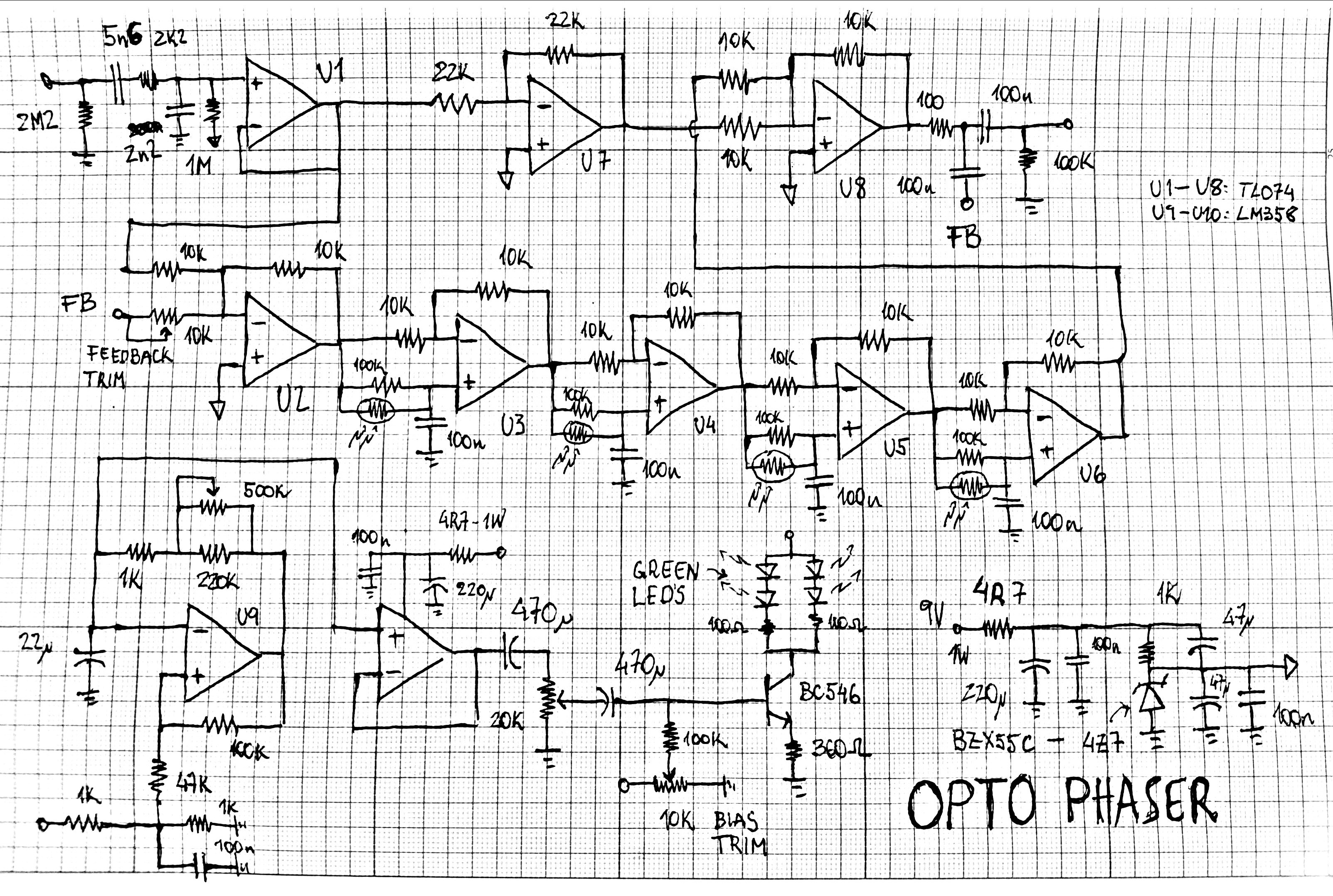
PS: as in the Balancer the zener is actually 4V3, though I don’t think it will make any difference.